 |
 |
 |
 |
 |
| |
|
|
|
|
|
| |
 |
|
| |
 |
 |
|
|
 |
|
|
|
|
|
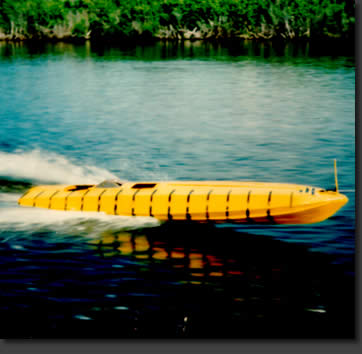
Developed by Mr. Jim Caldwell and Dr. Andrew Zborowski, the Constant Lift Configuration (CLC) hull concentrates on the aft third of a planing vessel's hull to reduce wetted surface without increasing the size of the vessel needed to carry the payload. |
|
|
 |
|
|
|
|
|
|
|
|
Typically, whilst moving from bow to stern, water travels out from keel to chine, but not in a straight path. The angle is directed by the amount of dead-rise and the speed at which the boat is moving. |
|
|
 |
|
|
|
|
|
|
|
|
A prevailing theory with high speed craft is: when you warp the hull, the warping effect causes the water to travel in a hook-shape. The hollow in the boat bottom makes the water travel a greater distance in that area and this creates drag, almost like a suction force. |
|
|
 |
|
|
|
 |
|
|
|
|
|
|
|
|
By incorporating convex twist to the hull, water flows optimally from keel to chine along the length of the planing surface. Mr. jim Caldwell Design Group has pateneted the formula for defining the amount of d4ead-rise change and the twist length for various perfromance objectives. This is referred to as the "Constant Lift Configuration Hull". |
|
|
|
|
|
|
|
 |
|
|
|
|
|
|
|
|
This formula allows the water to "see" the hull bottom as a smooth round surface (like an egg), allowing a reduced wetted surface without giving the hull an undesirable angle of attack through the water. This reduces friction and increases efficiency and performance of the boat. |
|
|
|
|
|
|
|
During model testing conducted at Steven's Institure in the USA, Mr. Caldwell stated that such hulls increase engine efficicieny by up to 15% at speeds between 6 and 40 knots. |
|
|
|
|
|
|
|
In 1987, a "generic 90-foot yacht" was compared to the C.L.C. hull with the same length and displacement ratios. Test results confirmed, breaking hte hull surface into a series of steps is the optimum way to reduce wetted surface for monhulls or catamarans. Steps provide fuel savings at all speed rangers but considering the engineering costs, creating a stepped hull for 25 to 30 knot boats is not cost effective. However, above 60 knots, a stepped hull becomes very cost effective increasing the overall efficiency by up to 25%. |
|
|
|
|
|
|
|
A stepped hull reduces wetted sufaces by creating high pressure areas on the front edge of the step, which lifts the hull and forms a "dry" area on the aft edge of the step. Channelling the steps reduces the inherent drag create by the dry area. |
|
|
|
|
|
|
|
The number of step on the hull is determined by the maximum speed required. Speeds up to 40 knots one step, 55 to 60 knots, two steps and for speeds up to 100 knots a vessel would require three steps. |
|
|
|
|
|
|
|
|
|
|
|
|
|
|
|


